The Opsys Communicator
The communicator is a background task launched by the Telecom session when GO.EXE starts. It requires a serial port through which it executes all activity between the PC and the local modem, reporting the current status and recent activity on-screen in the black area below the Telecom Session's Main Menu screen: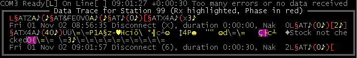
The Status Line
The Status Line indicates, in real time via the Ready and On Line boxes, what the communicator believes to be the current state of the modem on the indicated serial port. It also shows any details of the time of the last connection, its duration and the reason for going off-line. Here the modem is connected to the PC's serial port COM3 which is open with Channel code L but the modem is off line. The last connection occurred at time 09:01:27 and lasted for +0:00:30 (i.e. 30 seconds) when the communicator disconnected the call because Too many errors or no data received.
- The Ready [ ] box is empty, or shows a down pointing arrow
 , when the system is not ready to handle calls. When the system is ready to handle calls (or is currently handling one), the box shows the identification character for the current Channel between the PC and the modem. The communicator sets the PC's DTR (Data Terminal Ready) signal on or off according as the system is ready or not ready, respectively.
The modem must be configured to respond "normally" to DTR (usually controlled by the &D modem command), to ensure it will indeed drop the telephone line (i.e. go on-hook) whenever the system is not ready.
The communicator will go not ready if the modem's DCD (Data Carrier Detect) signal goes off for more than two seconds (or six seconds during data transfer). To attempt to ensure the modem reports loss of incoming carrier signal (from the remote modem) via the DCD signal it must be configured to control DCD "normally" (usually controlled by the &C modem command). - The On Line [ ] box is empty indicating off-line when the modem is not connected to the phone line, otherwise it shows a star
 indicating on-line. The modem cannot go on-line unless the Ready [ ] box indicates the system is ready.
 - The connection timer starts running when the local modem reports it has negotiated a connection (presumably with a remote modem) and stops when the communicator goes off-line.
The Data Trace Window
The Data Trace window (the boxed area in the snapshot) is a debugging tool giving a real time dump of all recent transfers between the PC and the local modem. The Station number in the title is the value of the PC Id field in the Change Settings dialog. The 8-bit character set used to display data within the window is that of the active Code Page (the MS-DOS command CHCP will identify the active Code Page). The dump is punctuated by red phase indicators and by time-stamped Disconnect messages which include the character code identifying the disconnection reason, the duration of the connection and the NAK count.
As the Data Trace window is quite small and cannot be scrolled, it only shows the most recent telecom activity. However, most client-end software retains a log file on its local disk of at least the most recent telecom session, and it can be vital to obtain this log to investigate a specific problem reported to you by a customer (see example).
| System | Log file |
|---|---|
| Mediphase (MS-DOS) | SAVECOM0.LOG in the C:\PHARM3\REO directory is the most recent. SAVECOM1.LOG is the next most recent, and so on. |
| Park | COMOUTIN.LOG |
| AAHP LS2 (Windows) | Understood to be TXTRACE.LOG in the \LINK\SCRIPTS\TEMP directory (or similar) |
Phase indicators (Red characters in the Data Trace Window)
| letter or number | The modem's serial port is being opened with the given channel setting. |
|---|---|
| § | A command is about to be sent to the modem (the command begins with the characters AT and ends with a carriage return). |
| ( | A result string is expected from the modem. Once the modem is correctly initialised, result strings will be numeric ending with a carriage return. ) indicates the communicator has recognised the end of the result string. If no result is received after one minute, the communicator reports an error. |
| [ | A result string is awaited from the modem, but there is no timeout. The data trace will end with [ when the communicator is waiting for the phone to ring. ] indicates the communicator has recognised the end of the result string. |
The NAK Count
The NAK count is the number of frames re-transmitted (by both ends) because the receiver detected an error. During the connection, the PC's speaker grunts each time the NAK count is incremented.
Connection
Either end may dial the connection. Both ends then place their modems on-line.
- A manual modem goes on line immediately upon detection of an incoming call, or when you press its DATA button.
- An AT-type modem goes on line in response to an Answer command from GO.EXE. The communicator sends this command immediately in response to a Ring result code from the modem, or when you press the Telecom Session's Break hotkey Ctrl+Fn (usually Ctrl+F2). It's also possible for another GO.EXE task to ask the communicator to put the modem on-line to dial a given telephone number, e.g. to support Calling Rota software.
- In either case, a modem cannot go or remain on line when the Ready [ ] box indicates not ready (the communicator prevents it doing so by turning the serial port's DTR signal off).
- To temporarily prevent an incoming call from being answered, select any option from the Telecom Session’s Main Menu which seizes the communicator (e.g. Configure Modem).
Once both ends have their modem on line, they attempt to agree the best mutually acceptable data transfer connection. This takes several seconds, during which time their negotiations should be audible. Given the developments in modem technology, the variety of modems that may be encountered and the options for configuring them, getting a connection can be a frustrating matter. The following considerations may help to increase the probability of success.
- Connection between modems requires one set to originate mode and the other set to answer mode. For Electronic Order Entry, GO.EXE’s local modem always operates in answer mode regardless of who dials the call.
- Neither end may use any other equipment on the phone line during a data connection. If the modem does not automatically disconnect your handset, ensure it is on-hook when the modem is on-line.
- The relative timing of when each modem is put on-line may determine whether they successfully negotiate a connection. To eliminate human meddling, have one modem dial the call and the other auto-answer.
- Do not restrict either modem's freedom to negotiate. If one end is restricted to 300bps negotiation, connection may be impossible. Special case: Client-end Windows software known as LS2 (LINK System 2) by AAH Pharmaceuticals.
The local modem reports a connection by turning its speaker off, raising DCD (Data Carrier Detect signal) and sending a numeric Result Code to the PC identifying the type of connection. The modem exits Command mode and enters Data mode thus establishing a physical connection for the transfer of data between the computers at each end. Depending upon the connection negotiated, the modems may or may not undertake error detection and correction.
A connection report does not necessarily imply that both modems have agreed the same connection, nor does it prove that there is a modem at the other end!
AT-type Modem Result Codes
| 0 | OK |
|---|---|
| 1 | Connect |
| 2 | Ring |
| 3 | No Carrier |
| 4 | Error |
| 5 | Connect 1200 |
| 6 | No Dial Tone |
| 7 | Busy |
| 8 | No Answer |
| 10 | Connect 2400 |
| >10 | Allocated by Manufacturer |
The "Hayes" or "AT" command set emerged as a de facto "standard" during the 1980s, when Hayes Microcomputer Products captured over 50% of the modem market. Originally, only the result codes 0-4 could occur (the connection speed did not require explicit mention as it could only be 300bps). The standard was soon extended to cover 1200bps and 2400bps, but thereafter manufacturers diversified and allocated their own codes. The additional codes usually also indicate which of any other factors such as error detection/compression schemes are in effect. Fortunately, the communicator does not need to interpret these codes provided it and the modem have locked (fixed) their own communication speed.
The fact that a command always begins with AT enables the modem to deduce the communicator's communication speed and other serial port parameters.
Disconnection
Either end may break a connection at any time, or some external event may intervene.
- The communicator monitors activity continuously and will take the modem off line when it believes that nothing useful will occur. A timed disconnect message appears in the data trace window with a one character code indicating the reason.
- AT-command type modems also monitor activity continuously and may take themselves off line (sometimes pre-empting the communicator).
- The local modem may be taken off line manually by pressing GO.EXE’s hotkey Ctrl+Fn, where n is session number for the Telecom Session (usually Ctrl+F2).
GO.EXE instructs the local modem to disconnect by dropping DTR (Data Terminal Ready signal) for two seconds (or until the Ctrl+Fn hotkey is pressed during this period).
Reasons for going off-line
| 0 | Far modem signal not detected The manual modem did not hear any remote modem's carrier signal within 30 seconds of being placed on line (an AT-type modem gives reason t or c below in such circumstances). |
|---|---|
| 1 | Local modem disconnected The modem's DSR signal was turned off. The modem may have been powered off or (if manual) have had its DATA button released. |
| 2 | Far modem signal lost or shut down The modem turned its DCD signal off and it remained off for two seconds (or six seconds during data transfer). |
| 3 | Far system did not answer frame During Transmit State the communicator sent a data-link frame several times but received no valid response. Suggests a connection quality or software problem. |
| 4 | Far system reported too many errors During Transmit State the communicator sent a data-link frame several time but received a negative acknowledgment on every occasion. Suggests a connection quality or software problem. |
| 5 | Far system did not answer enquiry The communicator sent a data-link enquiry code several times, but received no response. Suggests a connection quality or software problem. |
| 6 | Too many errors or no data received During Receive State the communicator sent several negative acknowledgments consecutively. Suggests a connection quality or software problem, but could be normal end of call if the remote end had nothing further to send. |
| 7 | Last frame received was too long The communicator received a frame longer than its allocated buffer size (around 544 bytes). Can occur if the modem makes a connection with dial tone or some other non-modem signal. |
| 8 | Far system ignored end of file During Transmit State the communicator sent the data-link EOT code several times but did not receive the expected response. |
| b | Line busy The communicator sent a Dial command but the AT-type modem reported Line Busy. |
| c | Remote carrier lost or never heard The AT-type modem reported No Carrier. |
| d | No dial tone The communicator sent a Dial command but the AT-type modem heard No Dial Tone. |
| e | Error in modem command The AT-type modem received a command it did not recognise. Check the communicator's Data Trace window for details. |
| r | Error in modem result Obsolete. Use a version of GO.EXE dated after 24 October 2002. |
| t | AT Modem timed out (no result) The communicator sent a command but received no response after one minute. Will occur after an Answer or Dial command if the modem has not sent any result code after one minute. |
| u | No answer The communicator sent a Dial command but the AT-type modem reported No Answer. |
| v | Error in modem configuration The AT-type modem responded incorrectly. This can happen if the modem has been reverted to an unsuitable configuration profile by being powered off/on (check that the Memorise field of the Change Settings dialog is set to 1). The communicator automatically reinitialises the modem two seconds after this disconnection. |
| A | Unknown process requested GO.EXE's Transport Layer has received a header frame it does not recognise. Possibly you are using an old version of GO.EXE which does not support a feature requested by the client-end. |
| B | Process unable to continue GO.EXE's Transport Layer unexpectedly cannot continue to handle the current process. For example, if the client-end is sending an order but GO.EXE runs out of hard disc space. |
| C | Process unauthorised to continue GO.EXE's Transport Layer does not have permission to perform the process requested by the client-end. For example, if the client-end fails to provide a required password. |
| X | Break forced locally The GO.EXE Telecom Session's Break hotkey (usually Ctrl+F2) was pressed whilst the modem was on line. |
| Z | End of call GO.EXE's Transport Layer protocol reached its specified conclusion. For example, if a protocol permits only one order to be handled per telephone call and this has been done. |
LINK System 2 (LS2)
It is understood that the current version of this client-end Windows program from AAH Pharmaceuticals requires that certain settings be pre-applied manually to the client-end modem through the Windows Control Panel. It is understood that AAHP's software installation procedure on the client-end computer includes the following steps in the Modems section of the Windows Control Panel:
- Add (by manual selection from a list) to the list of modems set up on the computer the Manufacturer (Standard Modem Type) Model Standard 300bps Modem. This imaginary modem must be assigned to the same computer port as the physical modem.
- In the Properties for the Standard 300bps Modem set the Connection preferences to 7 Data bits, Odd Parity and in the Advanced Connection Settings set Extra settings to &FE0M1X3 (this field may vary depending upon the actual physical modem).
Of course, the physical modem will already appear in the list of modems set up on the computer. AAHP state that this cannot be specified for communication with AAHP depots due to legacy 300bps answering equipment at the depots, which will have disconnected the caller before the much faster calling modem has negotiated down to 300bps. It is understood that the LS2 software is therefore configured to use the Standard 300bps Modem by default, presumably in the expectation that this will negotiate only for a 300bps connection. This approach may also be needed to avoid conflicts with other software using the physical modem.
Unfortunately and conversely, using the imaginary Standard 300bps Modem can be expected to prevent the LS2 software from negotiating a connection with your modem at the GO.EXE end. It is understood that AAHP's answer to this situation is to allow the LS2 user, when configuring supplier (wholesaler) details, to select from the list of modems set up on the computer which one is to be used when calling that supplier. Apparently, the AAHP help desk refers LS2 users to the supplier as regards setting up the presumably imaginary modem for that supplier. It would appear, therefore, that suppliers may be called upon by LS2 users to talk them through the Windows Control Panel sequence, followed by LS2 Supplier configuration.
It would seem that your options in this situation are either to ask the user to choose another Model from the list of Standard Modem Types, then apply similar Properties settings as at step (2) above, or to ask the user to choose the physical modem but apply the necessary Properties settings, reverting back as necessary in the event of conflict with other software.
Some Data Trace scenarios
Scenario 1
![]()
Here GO.EXE opened the PC's serial port with Channel Code L (115,200bps Answer Mode, the recommended value with a 56K modem and a Pentium PC) and the § indicates GO.EXE intends to send a command to the modem. However, the «CTS absent» warns that the communicator cannot detect the modem's Clear to Send signal at the serial port. Although the two characters AT are sent to the serial port's transmitter holding register all communications are stalled.
Check that the modem has power and is connected by the correct cable to the correct PC port.
Scenario 2
![]()
This is a typical AT-type modem initialisation sequence as executed by GO.EXE at start up. Here GO.EXE opened the serial port with Channel Code L (115,200bps Answer Mode), waited one-third of a second (the data trace does not indicate the duration of waits), sent the command ATZ (Reset modem), received a response, waited one second, sent the multiple command AT&FE0V0, received a response, waited two seconds, sent the null (empty) command AT, received the numeric result code 0. The final [ marks the start of an indefinite wait for some external event (such as an incoming telephone call).
- All AT-type modems have non-volatile memory into which a user configuration profile may be stored (usually by &W command), and the Reset command usually restores the most recently saved profile. In general we don't know what profile this may be, so a more reliable basis available with modern modems is to load a read-only factory configuration profile and then amend any unsuitable defaults. This is achieved here by the multiple command: &F is the contents of the Modem init field of the Change Settings dialog (here loading the modem's factory default configuration profile), after which GO.EXE always appends the commands E0 (Echo off) and V0 (Numeric result codes). This would have been followed by the command &W (Write current configuration profile) if the Memorise field of the Change Settings dialog had been set to 1 (which it should have been for a live installation).
- GO.EXE disregards the response from the first two commands, looking only for the terminating carriage return (shown as a musical note), as the state of the modem is unknown until it has been suitably configured. The A characters are the beginning of the command echo not yet turned off, which is discarded.
- The null command simply provokes the immediate numeric result code 0, meaning OK. It implicitly notifies the modem what speed and data format to use should it need to send a Ring result code.
Scenario 3
![]()
Two external events are shown here, interrupting an indefinite wait for the phone to ring.
First, the Telecom Session's Break hotkey (usually Ctrl+F2) was pressed on the PC's keyboard. The Break hotkey attempts to toggle the modem on or off line. Here the modem was off line so GO.EXE sent the command ATX4A (Answer). In the absence of an incoming call, dial tone and the modem's various answering tones should be audible. Assuming that the modem avoids making a connection with dial tone or any other tone on the line in the next minute, the communicator will time out the Answer command with reason code t.
However, on this occasion the Break hotkey was quickly pressed again. Because the modem was not connected to a remote modem (i.e. was still in Command mode), GO.EXE sent an arbitrary character (x) to take the modem off line in accordance with the AT-type modem command protocol, and the modem responded with result code 3 (No Carrier). Next, GO.EXE closed the serial port (turning DTR off) and issued the timed Disconnect message with reason code X (Break forced locally). As there was no connection with a remote modem, the duration and NAK counts were 0. After waiting two seconds, GO.EXE reopened the serial port with Channel Code L, sent a null command to reassert the serial port speed and data format, and resumed its indefinite wait for the phone to ring.
Forcing the modem on then off line with the Break hotkey is a quick way to check it is responding correctly and is connected to a live telephone socket (viz. you should hear dial tone).
Scenario 4

Wow! An order has been received and acknowledged and the phone line is now ready for the next call.
First, an incoming call caused the modem to send result code 2 (Ring). The communicator responded by sending the command ATX4A (Answer). After some seconds spent negotiating with the remote modem, the local modem responds with result code 40 (Connect).
- The communicator assumes that result codes 1, 5, 10 and all >10 report a connection with the remote modem. The different numbers represent different bit rates, error detection and data compression methods as specified (but not necessarily published) by the modem manufacturer.
- For older AT-type modems (Lock field in GO.EXE's Change Settings dialog is 0), the communicator now adjusts the PC's serial port speed to match the connection speed.
- For modern AT-type modems (specifically, any modem offering a result code >10 to report a connection) you must set the Lock field in GO.EXE's Change Settings dialog to 1 to prevent the communicator from adjusting the serial port speed. This is because the communicator does not know what the connection speed is when the result code is >10. If you have an early modern modem you probably need to have initialised it (as part of the Modem Init field of GO.EXE's Change Settings dialog) with the appropriate command to fix its serial port rate (possibly &B1 command, but check the manufacturer's documentation).
- After reporting the connection the modem switched from Command mode to Data mode (in accordance with AT-type modem command protocol). Therefore the remainder of the Data Trace shows the data passed between the software at each end, until the modem implicitly switched back to Command mode on disconnection.
With the communicator now in direct contact with the client-end software, it attempts to detect which of the supported data-link protocols the client-end is using (for background see the Opsys Protocol Handbook). The communicator does this by listening for client-end data. Whilst listening, it sends ASCII code SUB in even parity (hexadecimal 9A) at one second intervals. This code appears as Ü in the Data Trace:![]()
Most client-end software ignores the SUB codes (they are sent solely to support the Basic data-link protocol). On this occasion the client-end is using the Async data-link protocol, so it sends the Async RED$ code at two second intervals. This code appears as \= in the Data Trace. One such RED$ is sufficient for the communicator to recognise the Async data-link protocol; it stops sending SUB and responds with RED$ to assert it too is now in the Async protocol's Receive State, thus enabling the client-end to enter Transmit State:![]()
As Async is a binary file transfer protocol, it may not be immediately obvious that the above snapshot shows a complete two-line order sent under the P1 Transport Protocol. Look for the transitions between received data (bright yellow) and transmitted data (plain white). Here, two frames have been received (the Header Frame and a single Lines Frame). The communicator found each frame's trailing two-byte checksum valid, so it acknowledged both with the Async protocol's GREEN$ code (bearing in mind that GREEN$ alternates between ![]() and
and ![]() ). Having completed transmission of the order, the client-end exited to Receive State and resumed sending RED$ at two-second intervals. One such RED$ is sufficient for the communicator to enter Transmit State to send the P1 Transport Protocol's Outcome Report:
). Having completed transmission of the order, the client-end exited to Receive State and resumed sending RED$ at two-second intervals. One such RED$ is sufficient for the communicator to enter Transmit State to send the P1 Transport Protocol's Outcome Report:![]()
Here, two frames have been transmitted (a Progress Frame for Order Line 0 and the Order Outcome Frame). The characters with magenta background colour are the trailing two-byte checksums. The client-end software received each frame with valid checksum, so it acknowledged both with the GREEN$ code. Having completed transmission of the order outcome, the communicator exited to Receive State and resumed sending RED$ at two-second intervals (in case the client-end had another order or message to send):![]()
However, no valid response from the client-end was detected after several attempts, so the communicator cut the connection with reason code 6 (Too many errors or no data received). In fact, the client-end probably disconnected the call as soon as it received the first RED$, having found itself in Transmit State with nothing to send. Indeed, what looks like received noise in the above snapshot suggests that contact was lost.
Further consideration of this scenario leads to the conclusion that the local modem should have reported Carrier Lost under such circumstances, but this did not happen. Or did it? What was dismissed as noise now looks suspiciously like the modem's No Carrier result code. The communicator monitors the modem's DCD (Data Carrier Detect) signal for any change, but there is a modem command to override this signal. Usually, the command AT&C1 will set normal DCD operations, so let's change the Modem init field in GO.EXE's Change Settings dialog to &F&C1 and try again: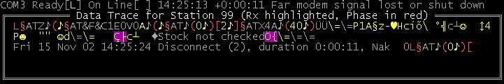
This is a significant improvement, as the connect duration has been reduced from 30 seconds to 11 seconds, meaning that the communicator will be ready to handle next incoming call 19 seconds earlier.
- The &C1 command is unnecessary if the Load Factory Default Configuration Profile command sets it anyway.
- It's not unusual for line disturbances to break a connection momentarily, so the modem waits a while (as determined by its S10 register) before reporting loss of carrier, whilst the communicator waits two seconds after detecting loss of carrier before it disconnects (or six seconds during data transfer).
Scenario 5
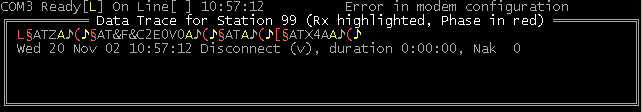
The Modem init field of the Change Settings dialog was set to the value &F&C2. The &F loaded the factory default configuration profile, but &C2 is an invalid command so the modem discarded the remainder of the command string leaving the Echo and Verbal commands not turned off. Consequently the communicator did not understand the modem's responses to subsequent commands. The communicator did not worry about this until it needed to interpret the response to its ATX4A command (Answer). Somewhat belatedly (you may consider) it disconnected with reason code v (Error in modem configuration). Two seconds later (but not shown above) the communicator attempted to initialise the modem again (but with the same effect).
When the communicator detects an echo from the modem it discards subsequent received data up to a carriage-return code, and the discarded data is not shown in the Data Trace. A version of GO.EXE dated after 20 November 2002, however, shows the discarded data in the Data Trace: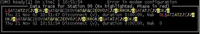
Also, the communicator now checks the response to the AT command (Null) following modem initialisation and promptly disconnects if it is not understood (as shown above). This process will repeat indefinitely at about seven-second intervals, and the Status line will (correctly) never show modem Ready.
Scenario 6
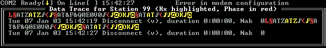
Here the communicator continuously reported Error in modem configuration because the Psion Dacom V34 Gold Card modem was responding verbally and with echo rather than numerically to the AT command (Null), even though the modem OK'd the preceding command which included E0V0 requesting no echo and numeric respones.
The solution to this irritation was to preset the modem into numeric response mode by manually typing the command ATE0V0&W in option C Configure Modem from the Telecom Session's Main Menu.